
CREATION OF A PROSTHETIC FOOT FOR THE STUDY OF THE FIELD SHOE INTERACTION
25/06/2018
Johan RAVAIL
Thibaud LUCK
HIGHLIGHTING THE PROBLEM
The study of field shoe interactions is a subject in the field of sport. Indeed, many brands of sports equipment manufacturers are very interested in the work done to allow them to offer the best product on the market. But what do we mean by better product? Indeed, we do not expect crampons from a pillar of a rugby team the same performances as the tips of a 100m sprinter, nor basketball shoes the same performances as those of a marathon runner. That’s why we had to establish a framework for our project.
We chose to focus on Basketball and more particularly on an injury very common in this sport: the sprained ankle.
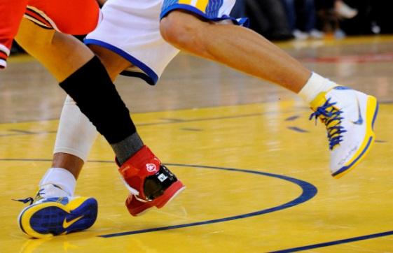
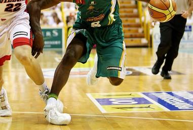 Figure 1 – Image of ankle sprains on professional basketball players
A study carried out over 20 seasons and 3 divisions of American college basketball, showed that ankle injuries represent 26% of injuries during games or practices (far ahead of knee injuries 9% that come in2nd place) and 90% of these ankle injuries are tibio-fibularsprains(National Collegiate Athletic Association Injury Surveillance System, 1988–1989 Through 2003–2004)
This injury occurs in the vast majority of cases during a rapid change of directions, in defense and attack, as can be seen in the examples above.
ISSUE STUDIED
In view of the previous information it seemed wise to study the influence of pairs basketball shoes – basketball court during a movement associated with this injury, often recurrent even in the greatest players (eg Stephen Curry …).

Figure 2 – Definition of the problem
The problem of this project can therefore be summarized in:
Creation of a prosthetic foot for the study oftibio-fibular sprain in basketball
DELIVERABLE
We have set ourselves the following specifications:
- prosthetic foot for basketball shoes in size 49;
- adapted to the robot arm of the static test room;
- resistant to arm loads on the parquet square;
- allowing the recovery of the efforts applied to the external collateral ligament.
APPROACH ENVISAGED
After having sought to design a prosthetic foot faithfully representing the mechanics of a human foot thanks to different existing models in biomechanics (such as Lelièvre, Dolto, De Doncker …), we refocused on the problem of our project.
We decided to simplify our foot modeling as much as possible. Kinematic and dynamic studies of the studied movement allowed us to refine the mechanical design of our ankle.
Thanks to a scan of a foot The most complex part was the simulation of the actions of the different ligaments on the ankle during this movement and the way to make the parallel in the efforts recovered on our prosthetic foot and those actually cashed by the ligament.
Then comes the realization of the prosthetic foot: 3D printing of the foot and machining of the pivot link. Another rather complex part of the project will be to control the robot in order to make it realize the movement to be analyzed.
Once all these steps have been completed,different tests can be carried out and the data collected at the sensor level can beanalyzed according to the parameters involved (shoe model and type of terrain).
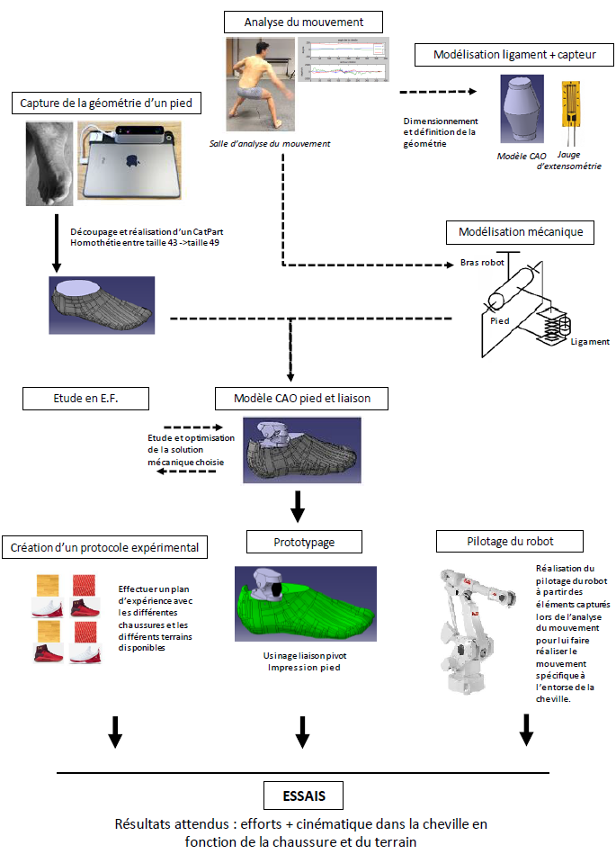
Figure 3 – Details of the approach initially envisaged
KINEMATIC MODELING
ANKLE
The ankle is composed of several contact zones that allow its movement. The 3 main bones that make up the ankle are the Fibula,the Tibia and the Talus.
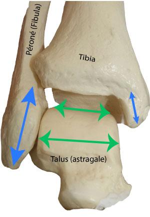
Figure 4 – Bones and contact surfaces in the ankle

Figure 5 – Initial position – Dorsiflexion – Plantar flexion

Figure 6 – Initial position – Supination – Pronation
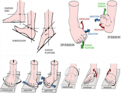
Figure 7 – Initial position – Adduction – Abduction
Final modeling
The movement we seek to study is actually an ankle inversion. This movement is a combination of flexion, adduction and supination of the ankle.

Figure 8 – Reversal motion
In order to simply achieve this movement, we opted for the realization of a single pivot link. This hypothesis is very simplifying but we decided to go in this direction. We will criticize all our assumptions at the end of the report.

Figure 9 – Kinematic diagram of the connection between the foot and the robot
CINEMATIC AND DYNAMIC ACQUISITION
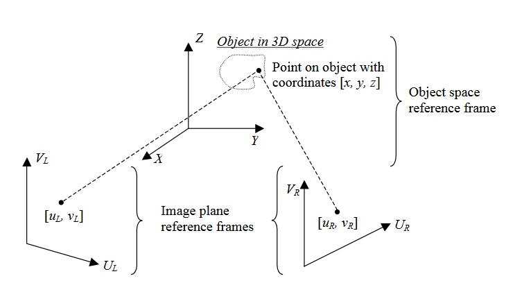
To size our foot we need to obtain kinematic results on the ankle as well as results of efforts in the center of the ankle.
The kinematic analysis of the sporting gesture consists in describing the movements of the body and its segments that occur at given moments, in specific places in space.
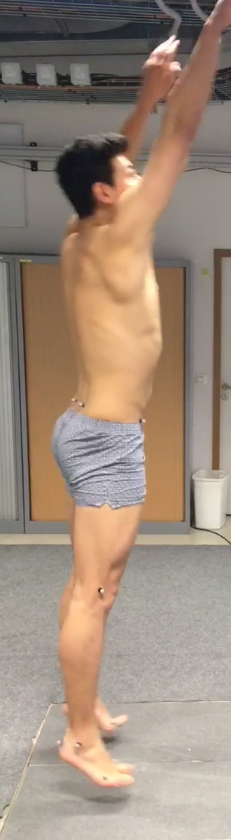
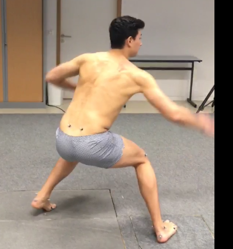
It is obvious that the results we obtained are imprecise because we used the bare minimum in terms of sensors to be able to reconstruct the body segments from the feet to the hips.
What interests us in this crossover movement is exclusively on the foot that is most prone to sprains for us the right foot.
Acquisitions:
It is the complete movement that consists of making a brutal support that cuts the speed forward suddenly to go back and then shoot the ball, this movement having the aim of putting at a certain distance the defender to give himself time to prepare his shot.
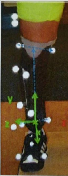
Movement analysis project : Direct linear transformation movement analysis at the Georges Charpak institute using Matlab and infrared markers. Used to record constraints and stresses for the design of a prosthetic foot.
Results:
To extract the results we used the Matlab algorithms belonging to the laboratory(toolbox),including the one created to study the walk of a child. ![]()
![]()
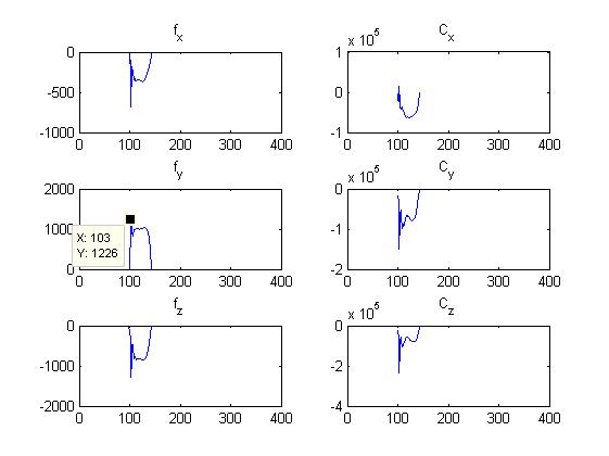
We are interested in the time period of 100 to 160 hundredths of a second which corresponds to the moment when the foot performs the most traumatic part, that is to say the change of direction.
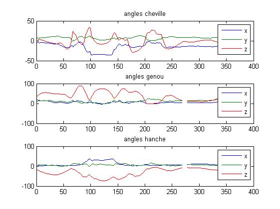
Ankle angles:
When the ankle is at rest there is an angle of 5 ° between the tibia mark and the foot mark. Once the foot touches the ground the angle passes to a maximum of 36 ° in a rather brutal way. We will therefore size our foot so that it can go up to 45 ° to oversize.
Efforts within the ankle:
(We are looking for an equivalent model rather than exhaustively reproducing the articulation).
What interests us in our simplified model is to impose a torque OR a displacement on our prosthetic foot and, thanks to a device, to recover the stresses and deformations on the material replacing the ligament.
Here we obtain a maximum of Cx = 6.5E04 N.mm the torque that will generate the sprain preponderantly.
A result in Y and Z of approximately 1230 Newton is obtained.
Model Critique:
We must not forget that it is when we carry out the acquisition the model realizes the movement properly flatfoot.
It is precisely when the foot revolves around X that a huge moment is created on the ankle because a large part of the weight of the athlete becomes a force with a lever arm in relation to the ankle.
CAD MODELING
FOOT
Thanks to an optical scan
We scanned a foot about 275 mm in length.
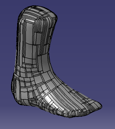
Figure 10 – CatPart of the scanned foot
But we wanted to have a foot size 49 in order to fit in a basketball shoe. The sizes differ according to the shoe manufacturers so we chose to base ourselves on the famous brand of basketball shoe resulting from a partnership in a former great player of the Bulls and the company to the comma.

Figure 11 – Air Jordan Brand Size Guide
We therefore considered that a foot of size 43 was, with one homothety, the same as a foot of size 49. The ratio was:
Thus we get the following foot:
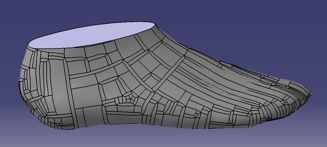
Figure 12 – CAD part of the foot in size 49
ANKLE
We decided to make a single pivot link between our prosthetic foot and the robot axis. The orientation of this link will depend on the movement we want to simulate on the robot.
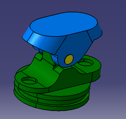
Figure 13 – CAD solution of our ankle
The green part is the part that will be connected to the foot below. We will explain the cylindrical part of its shape when presenting the foot/green coin connection. The axis hole will serve as a guide for the pivot link. The 2 non-opening holes will be used to fix the materials performing the stiffness of our ankle.

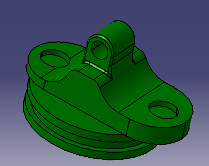
Axis nesting in the axis hole mentioned above.

Part of our ankle that will attach to the arm of the robot. It also has two notches where the materials ensuring the stiffness of the ankle will come to position.
PIVOT MOUNTING ON STAND

Figure 14 –

We thought of putting holes for pressure screws in order to be able to adjust the angular position of the axis of the pivot link according to the movement to be studied.